Type E Bearings Overview
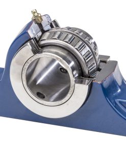
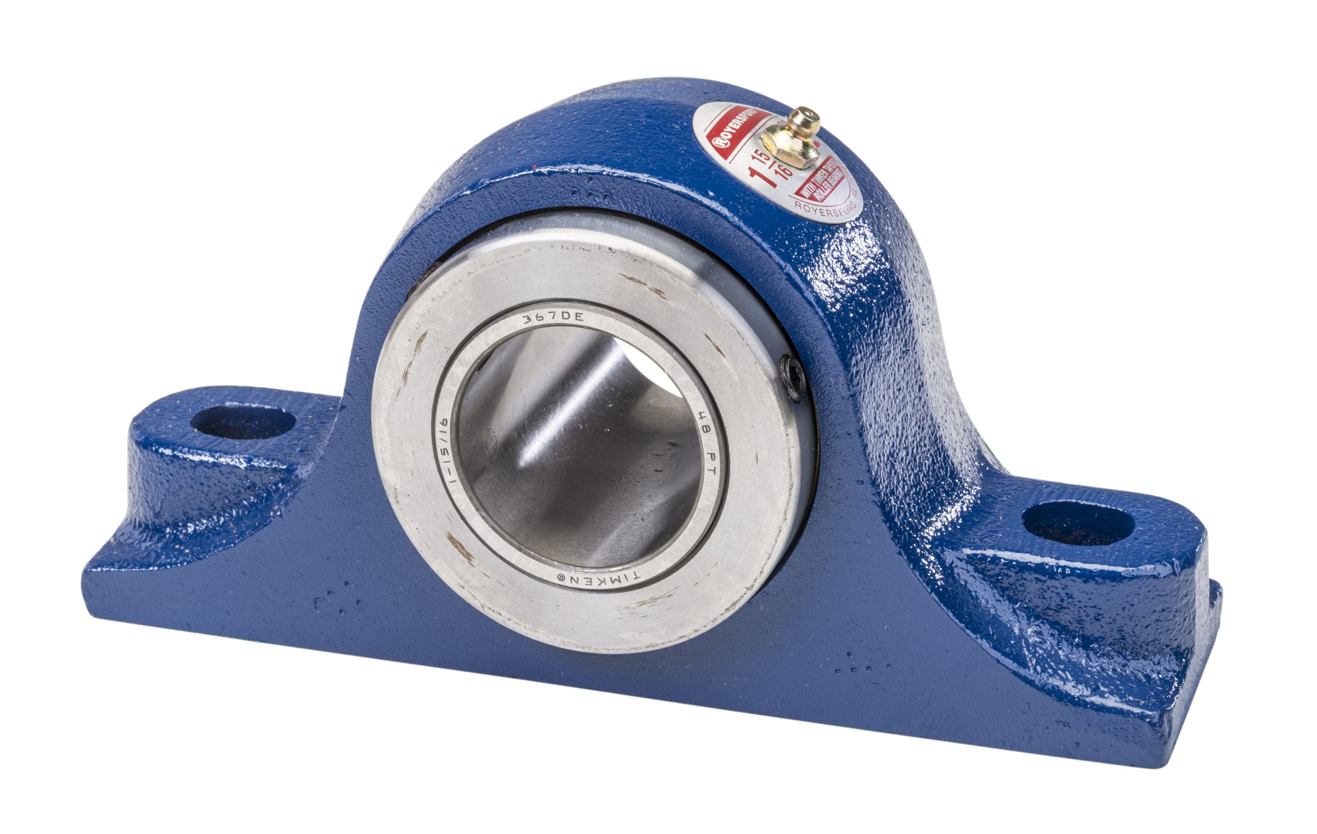
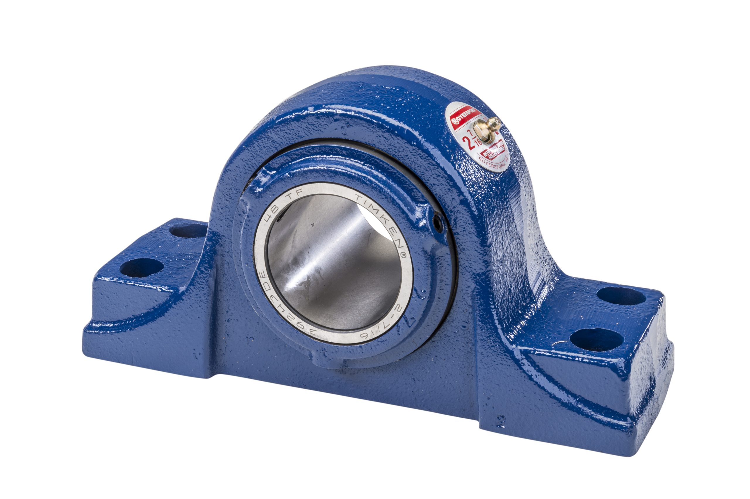
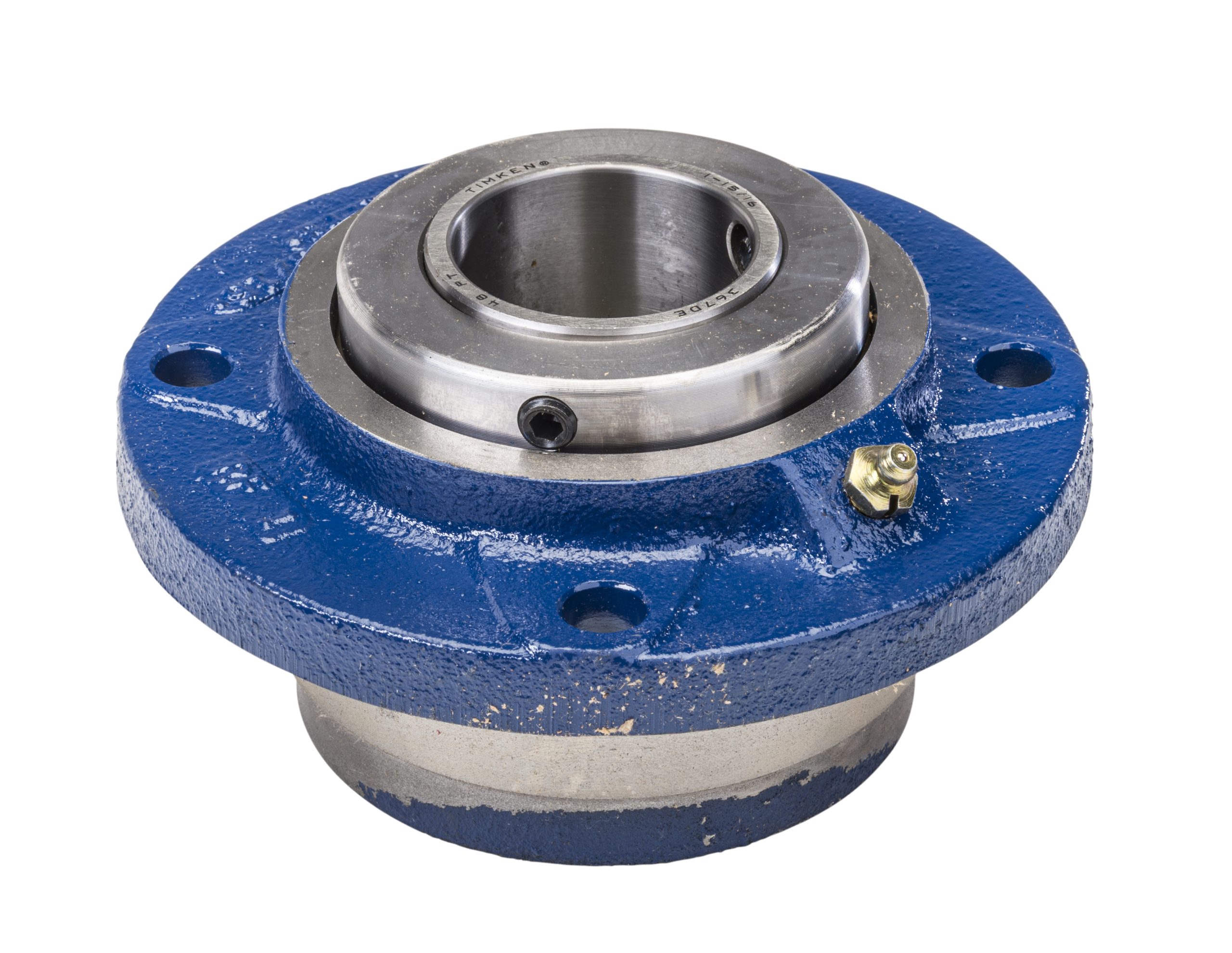
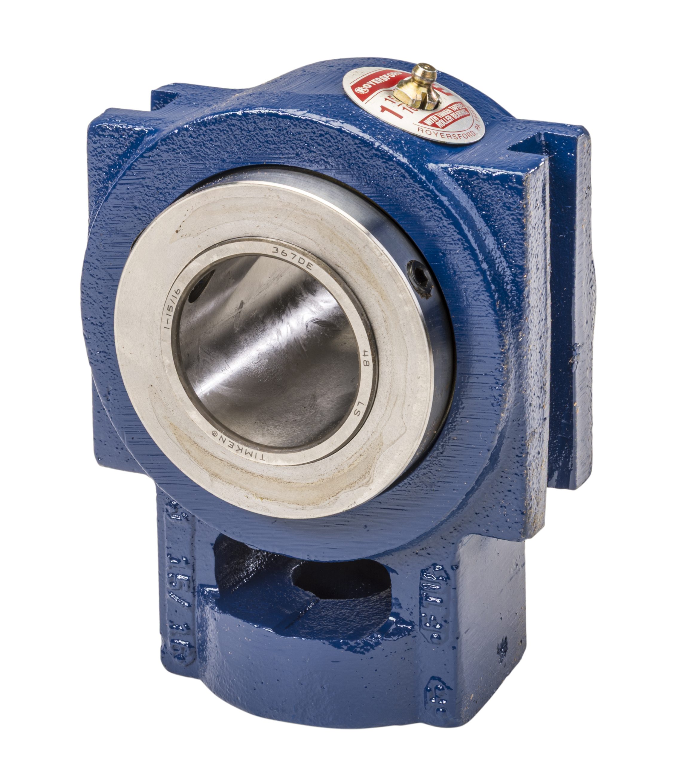
Royersford Type E mounted bearings are built for high-speed, heavy-duty industrial applications where durability and dependable shaft locking matter most. Made in the USA with compact, rugged gray iron housings and premium Timken tapered roller bearings; these units deliver exceptional load capacity, long service life, and quick, contamination-free installation. Available in shaft sizes from 1 3⁄16” through 5” and widely stocked throughout the US and Canada.
Key Benefits:
- Perfect for applications with high radial and thrust loads with minimal misalignment
- Positive locking collars + set screws for secure shaft engagement
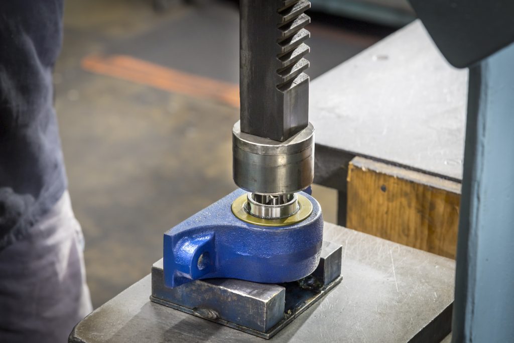
- Factory assembled, sealed, and lubricated– install in minutes with minimal downtime
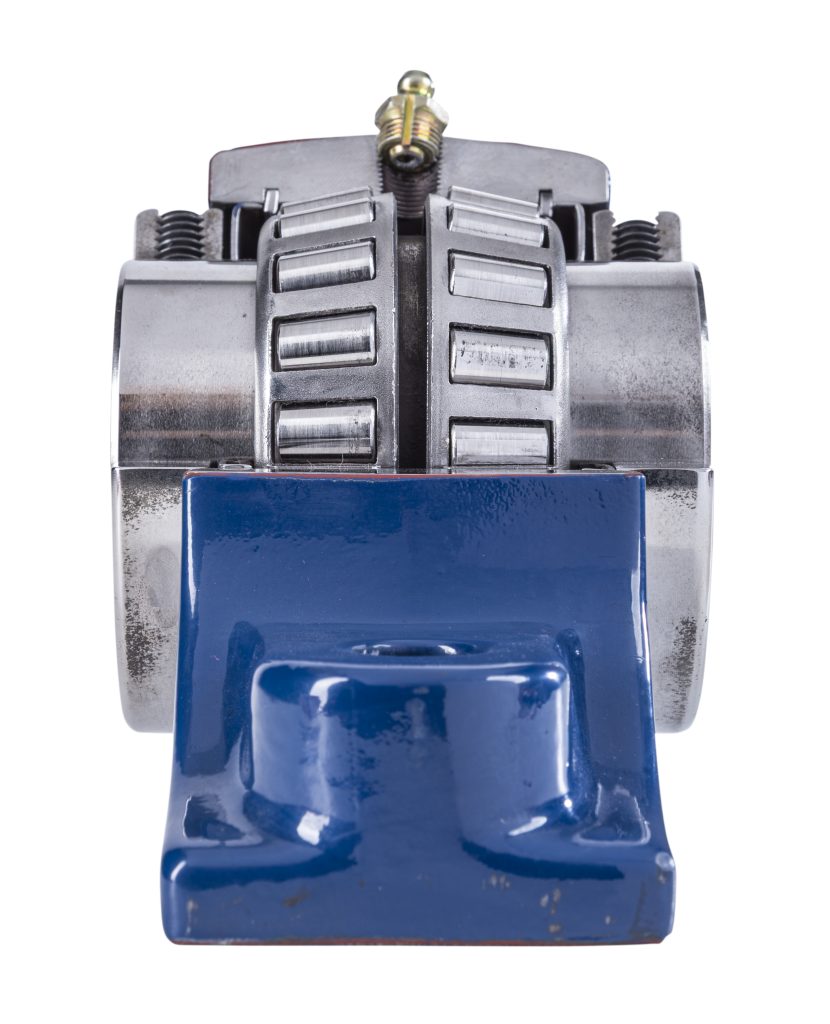
- Timken tapered roller bearings for superior radial & thrust load capacity
Why Timken Tapered Roller Bearings Stand Out:
- Timken tapered inserts deliver robust performance in demanding applications
- Vacuum-degassed steel for long service life
- Excellent balance of radial and thrust load handling
- Long inner race distributes load evenly
- Designed to handle slight angular misalignment
These attributes give Royersford Type E bearings a performance edge that reduces downtime and boosts overall reliability.
Materials & Construction:
- High-strength gray iron housings, made in the USA
- Compact footprint without sacrificing ruggedness
- Fully machined mounting surfaces for precise alignment
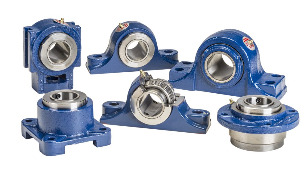
- Available in 2 and 4-Bolt pillow blocks, square and piloted flanges, and Take-Up units
Shaft Locking System
- Dual ductile iron collars secure the inner race
- Two set screws provide additional holding strength
- Prevents slippage in high-load or high-vibration environments
Sealing System
- Dual-lip light contact seals
- Primary lip retains lubrication
- Secondary lip blocks dirt, dust, and moisture
- Seal efficiency is maintained across the full self-alignment range
- Locking collars “sling” contaminates away from seals
Installation Advantages
- Delivered pre-lubricated, pre-sealed, and pre-adjusted
- Eliminates contamination during setup
- Reduces downtime
- Simplifies Maintenance
- Avoids premature failure
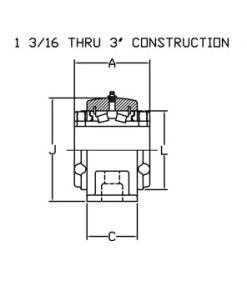
Technical Specs:
- Race adjust: Snap rings + shims on units up to 3”
- Adjustment nut on sizes 3 3⁄16” to 5”
- Bore tolerance:
- (+.001” / -.000” for bores less than 3”)
- (+ .002” / -.000” for bores greater than 3”)
- Units are fully factory assembled, sealed, and lubricated
Common Industry Applications & Equipment Uses
Include but are not limited to:
- Conveyors and Conveyor Drive Systems
- Gear Reducers & Gearboxes
- Crushers, Pulverizers, & Mills
- Mixers, Agitators, & Processing Equipment
- Fans, Blowers, Pumps, & Compressors
Type E Bearing Products
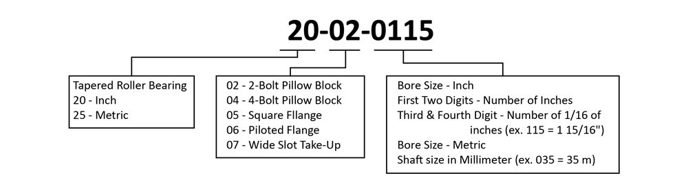
Type E Bearing Nomenclature
*All standard units include suffix -501
**Additional suffixes (5XX) will be used to designate modified or special assemblies
Component & Replacement Kit Nomenclature
Selection
Royersford Type E tapered roller bearings are engineered to handle heavy radial, thrust, and combined radial/thrust loads. The maximum recommended load depends on the bearing, housing, shaft, shaft attachment, speed, and life requirements listed in this catalog.
Selection Method:
- Calculate the Equivalent Radial Load (P) for your application.
- Choose a Type E bearing from the selection chart with a radial load rating at the operating speed that is equal to or greater than the calculated Equivalent Radial Load for the desired L₁₀ life.
- This selection method meets the needs of most general applications and covers occasional average shock loads.
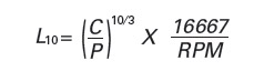
L₁₀ Life:
- L₁₀ Life is the number of operating hours that at least 90% of identical bearings are expected to achieve under the same load and speed conditions
- For L₁₀ lives other than those listed in the selection chart, multiply the Equivalent Radial Load by the appropriate factor (for example, 1.16 for 50,000 hours and 1.34 for 80,000 hours) and then select a bearing with a rating equal to or greater than that value.
Heavy Service:
- For heavy or frequent shock loads and severe vibration, increase the Equivalent Radial Load by up to 50% based on severity before selecting a bearing.
Thrust Loads:
- The thrust values in the tables are intended as general guidelines for adequate L₁₀ life.
- If a significant radial load is also present, calculate the L₁₀ life to ensure it meets your requirements.
- Do not exceed the maximum thrust loads shown in the associated thrust load tables.
- Bearing effectiveness under thrust load also depends on proper shaft attachment, set screw tightness, shaft tolerances, and deflections; use auxiliary thrust components (e.g., shaft shoulder, thrust collar) for heavy thrust loads or high reliability.
Shaft and Housing Considerations:
- Shaft tolerances recommended in the tables are suitable for normal radial, thrust, and combined loads.
- Heavy loads should be directed appropriately through housings (e.g., through the base for pillow blocks), and housing/bolting strength should match load direction.
- Use auxiliary load devices (shear bars, collars) for side or end loading on pillow blocks and flange units.
Where:
- L 10 = Life hours
- C90 = Dynamic Capacity, lbs. (Table 1)
- P = Equivalent Radial Load, lbs.
Equivalent Radial Load (P):
- When only radial load is present, P = radial load (Fᴿ).
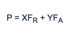
- For combined radial and thrust loads, compute using P = X·Fᴿ + Y·Fₐ, where X and Y are radial and thrust factors from the tables, based on the thrust-to-radial load ratio.
Where:
- P = Equivalent radial load, lbs.
- F R = Radial load, lbs. - (See Table 1 for allowable slip fit maximum)
- F A = Thrust (axial) load, lbs.
- e = Thrust load to radial load factor (Table 1)
- X = Radial Load Factor from table 1
- Y = Thrust Load Factor from table 1
Table 1 - Radial/Thrust Factors
Table 2 - Radial Load Ratings in Pounds
*"Minimum Hours Life" is the life which may be expected from at least 90% of a given group of bearings operating under identical conditions. The average life will be approximately five times the minimum life.
Note: Because the allowable loads, especially at low speeds, are extremely high, be sure that the shaft strength is adequate and pillow blocks are base loaded. When the load line falls outside the base, fastener and housing deflection or failure may occur. These conditions require designs using proper engineering principles applied to materials, fasteners, mounting and etc. with adequate safety factors.