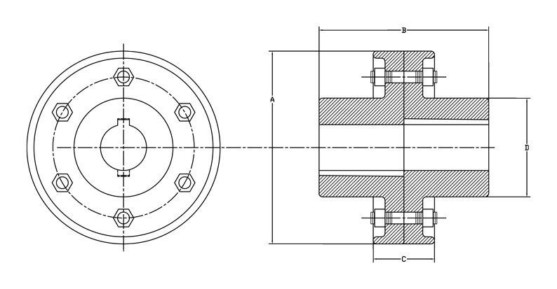
Rigid Flange Couplings
This style coupling is used where the smallest overall length is necessary and ease of installation is not a factor. Couplings are fitted to the shafts and use tapered keys. Shaft sizes of 3 11/16 inches and above have male and female type construction.
|
Shaft |
Part Number |
Weight |
A |
B |
C |
D |
Keyway |
Bolts |
|
|---|---|---|---|---|---|---|---|---|---|
|
No. |
Size |
||||||||
|
15/16 |
60-07-0015 |
6.0 |
4 7/8 |
3 1/4 |
1 5/8 |
1 7/8 |
1/4 |
3 |
1/2 |
|
1 3/16 |
60-07-0103 |
16.5 |
6 3/4 |
4 7/8 |
2 1/8 |
2 3/4 |
1/4 |
4 |
1/2 |
|
1 7/16 |
60-07-0107 |
25 |
7 5/8 |
5 5/8 |
2 3/8 |
3 3/8 |
3/8 |
5 |
1/2 |
|
1 11/16 |
60-07-0111 |
36 |
8 3/8 |
2 1/2 |
2 1/2 |
4 |
3/8 |
5 |
5/8 |
|
1 15/16 |
60-07-0115 |
49 |
9 |
7 3/8 |
2 7/8 |
4 1/2 |
1/2 |
5 |
5/8 |
|
2 3/16 |
60-07-0203 |
59 |
9 1/2 |
8 1/4 |
3 |
5 |
1/2 |
5 |
5/8 |
|
2 7/16 |
60-07-0207 |
70 |
10 1/4 |
9 |
3 1/4 |
5 1/4 |
5/8 |
6 |
5/8 |
|
2 15/16 |
60-07-0215 |
98 |
10 7/8 |
10 |
3 1/4 |
6 1/4 |
3/4 |
6 |
3/4 |
|
3 7/16 |
60-07-0307 |
120 |
12 1/4 |
10 7/8 |
3 3/8 |
6 3/4 |
7/8 |
6 |
3/4 |
|
3 15/16 |
60-07-0315 |
160 |
13 |
11 1/8 |
3 7/8 |
8 |
1 |
6 |
3/4 |
|
4 7/16 |
60-07-0407 |
190 |
14 3/8 |
1 3/8 |
4 1/8 |
8 1/2 |
1 |
6 |
7/8 |
|
4 15/16 |
60-07-0415 |
375 |
16 1/2 |
13 7/8 |
5 3/4 |
10 1/2 |
1 1/4 |
8 |
7/8 |
|
5 7/16 |
60-07-0507 |
450 |
17 3/4 |
14 3/4 |
6 |
10 3/4 |
1 1/4 |
8 |
7/8 |
|
5 15/16 |
60-07-0515 |
530 |
19 |
16 |
6 1/2 |
11 1/4 |
1 1/2 |
8 |
1 |
All flange couplings are made to order. Sizes not listed, Reducers, Special Keyways, Male & Female Construction, and Metric Bores are priced upon request. Flange couplings are made with undersized bores for a press fit unless otherwise requested.
